NikonUSA NikonNet MicroscopyU NikonMall NikonSchool
Search
Go

Principles of Phase Contrast Microscopy

Differences in light absorption are often negligible between living cells and their surrounding nutrient medium, as well as between the various intracellular components and plasma membranes, rendering these entities barely visible when observed by brightfield illumination. Phase contrast microscopy takes advantage of minute refractive index differences within cellular components and between unstained cells and their surrounding aqueous medium to produce contrast in these and similar transparent specimens.

Phase Contrast Microscopy - Phase contrast microscopy, first described in 1934 by Dutch physicist Frits Zernike, is a contrast-enhancing optical technique that can be utilized to produce high-contrast images of transparent specimens such as living cells, microorganisms, thin tissue slices, lithographic patterns, and sub-cellular particles (such as nuclei and other organelles). In effect, the phase contrast technique employs an optical mechanism to translate minute variations in phase into corresponding changes in amplitude, which can be visualized as differences in image contrast. One of the major advantages of phase contrast microscopy is that living cells can be examined in their natural state without being killed, fixed, and stained. As a result, the dynamics of ongoing biological processes in live cells can be observed and recorded in high contrast with sharp clarity of minute specimen detail.

Specimen Contrast in Optical Microscopy - Light can interact with a specimen through a variety of mechanisms to generate image contrast. These include reflection from the surface, absorption, refraction, polarization, fluorescence, and diffraction. Contrast can also be increased by physical modification of the microscope optical components and illumination mode, as well as manipulation of the final image through photographic or digital electronic techniques. The discussion in this section highlights various interactions between the specimen and light, and reviews some of the optical microscopy techniques that have been developed to enhance specimen contrast.

Apodized Phase Contrast - An unfortunate artifact in phase contrast microscopy is the halo effect, which results in spurious bright areas around phase objects or reverse contrast in images. This effect is especially prevalent with specimens that induce large phase shifts. Reducing the halo artifact was once thought to be a difficult theoretical problem, but recent advances in objective phase ring configuration have resulted in a new technique termed apodized phase contrast, which allows structures of phase objects having large phase differences to be viewed and photographed with outstanding clarity and definition of detail.

Phase Contrast Microscope Configuration - Phase contrast optical components can be added to virtually any brightfield microscope, provided the specialized phase ring objectives conform to the tube length parameters, and the condenser will accept an annular phase ring of the correct size. The major manufacturers all provide phase contrast accessories for their research and teaching-level microscopes, both in upright and inverted (tissue culture) configurations. This section outlines the necessary equipment for observing specimens in phase contrast illumination and discusses basic steps in microscope alignment.

Interactive Java Tutorials

Phase Contrast Microscope Alignment - Careful alignment of the phase contrast microscope is essential to produce the maximum contrast effect without introducing artifacts that degrade specimen appearance. This interactive tutorial examines variations in how specimens appear through the eyepieces (at different magnifications) when the condenser annulus is shifted into and out of alignment with the phase plate in the objective.

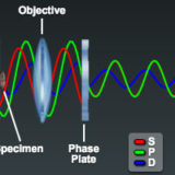
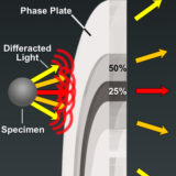
Optical Pathways in the Phase Contrast Microscope - The most important parameter in the design of a phase contrast microscope is to isolate the surround and diffracted light waves emerging from the specimen so that they occupy different locations in the diffraction plane at the rear aperture of the objective. This interactive tutorial explores light pathways through a phase contrast microscope and dissects the incident electromagnetic wave into surround (S), diffracted (D), and resultant (particle; P) components.

Phase Plate Configuration Effects on Specimen Contrast - The transmission and retardation properties of surround (undiffracted) light passing through the phase plate annulus in phase contrast microscopy can significantly affect the overall specimen contrast observed in the microscope. This interactive tutorial explores contrast variations induced by altering phase plate absorption and retardation characteristics.

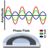
Positive and Negative Phase Contrast - Depending upon the configuration and properties of the phase ring positioned in the objective rear focal plane, specimens can be observed either in positive or negative phase contrast. This interactive tutorial explores relationships between the surround (S), diffracted (D), and resulting particle (P) waves in brightfield as well as positive and negative phase contrast microscopy. In addition, phase plate geometry and representative specimen images are also presented.

Specimen Optical Path Length Variations - Phase contrast microscopy interprets differences in specimen optical path length as fluctuations in light intensity, which are readily observed as variations in contrast through the microscope. This interactive tutorial explores the effects of refractive index and thickness changes on the apparent overall optical path length, and demonstrates how two specimens can have different combinations of these variables but still display the same path length.

Interaction of Light Waves with Phase Specimens - Upon encountering a phase specimen, an incident illumination wavefront is deformed according to the geometry, refractive index, and thickness of the specimen. This interactive tutorial examines the variety of deformations observed in wavefront shape as specimens having differing characteristics are illuminated with a planar beam of light.

Shade-Off and Halo Phase Contrast Artifacts - Two very common effects observed in phase contrast images are the characteristic shade-off and halo patterns in which the observed intensity does not directly correspond to the optical path difference (refractive index and thickness values) between the specimen and the surrounding medium. This interactive tutorial demonstrates shade-off artifacts in positive and negative phase contrast microscopy.

Apodized Phase Contrast - In apodized phase contrast microscopy, halo attenuation and an increase in specimen contrast can be obtained by the utilization of selective amplitude filters located adjacent to the phase film in the phase plates built into the objective at the rear focal plane. These amplitude filters consist of neutral density filter thin films applied to the phase plate surrounding the phase film as illustrated in the tutorial window.

Apodized Phase Plates and Specimen Contrast - Recent advances in objective phase ring configuration have resulted in a new technique termed apodized phase contrast, which allows structures of phase objects having large phase differences to be viewed and photographed with outstanding clarity and definition of detail.

Phase Contrast Digital Image Galleries

Phase Contrast Digital Image Gallery - Transparent specimens often appear remarkably different when comparatively observed under positive and negative phase contrast illumination. In positive phase contrast, specimen intensity is manifested by relatively medium to dark gray features, surrounded by a bright halo, and superimposed on a lighter gray background. Alternatively, in negative phase contrast, the specimen often appears much brighter on a dark gray background and the accompanying halos are also dark (much darker than the background). This digital image gallery compares identical viewfields of a wide variety of specimens illuminated with both positive and negative phase contrast.

Phase Contrast and DIC Comparison Image Gallery - Phase contrast and differential interference contrast (DIC) should be considered as complementary (rather than competing) techniques, and employed together to fully investigate specimen optical properties, dynamics, and morphology. In many cases, each technique will reveal specific details about a particular specimen that is not apparent from observing images captured by other methods. The wide variety of images presented in this gallery are derived from both thick and thin transparent specimens, as well as specimens that have inherent contrast originating from synthetic dyes (stains) or natural pigments.

Selected Literature References

Phase Contrast References - A number of excellent books, review articles, and original research reports on phase contrast microscopy have been published by leading researchers in the field and were utilized as references to prepare the phase contrast discussions included in the MicroscopyU website. This section contains periodical location information about these articles, as well as providing a listing of selected original research reports and books describing specimen contrast and the classical techniques of phase contrast light microscopy.

Contributing Authors

Douglas B. Murphy - Department of Cell Biology and Anatomy and Microscope Facility, Johns Hopkins University School of Medicine, 725 N. Wolfe Street, 107 WBSB, Baltimore, Maryland 21205.

Ron Oldfield - Department of Biological Sciences, Division of Environmental and Life Sciences, Macquarie University, New South Wales 2109, Australia.

Stanley Schwartz - Bioscience Department, Nikon Instruments, Inc., 1300 Walt Whitman Road, Melville, New York 11747.

Greenfield Sluder - Department of Cell Biology, University of Massachusetts Medical School, 377 Plantation Street, Worcester, Massachusetts 01605.

Tatsuro Otaki - Optical Design Department, Instruments Company, Nikon Corporation, 1-6-3 Nishi-Ohi, Shinagawa-ku, Tokyo, 140-8601, Japan.

Matthew Parry-Hill, Robert T. Sutter, Cynthia D. Kelly, Shannon H. Neaves, Omar Alvarado, and Michael W. Davidson - National High Magnetic Field Laboratory, 1800 East Paul Dirac Dr., The Florida State University, Tallahassee, Florida, 32310.